Phase 01
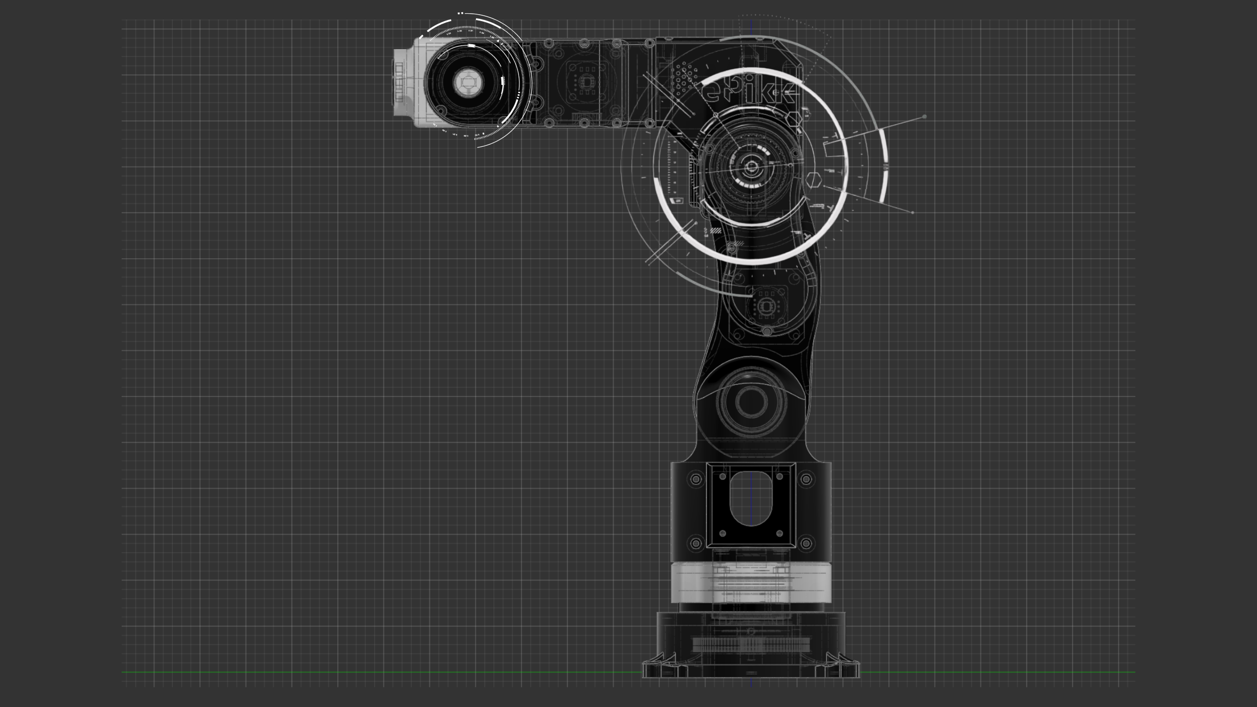
Kinematic Architecture & System Definition
Phase 02
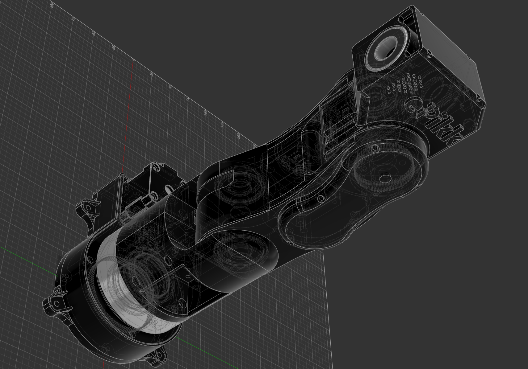
3D Modeling & Structural Design Optimization
Phase 03
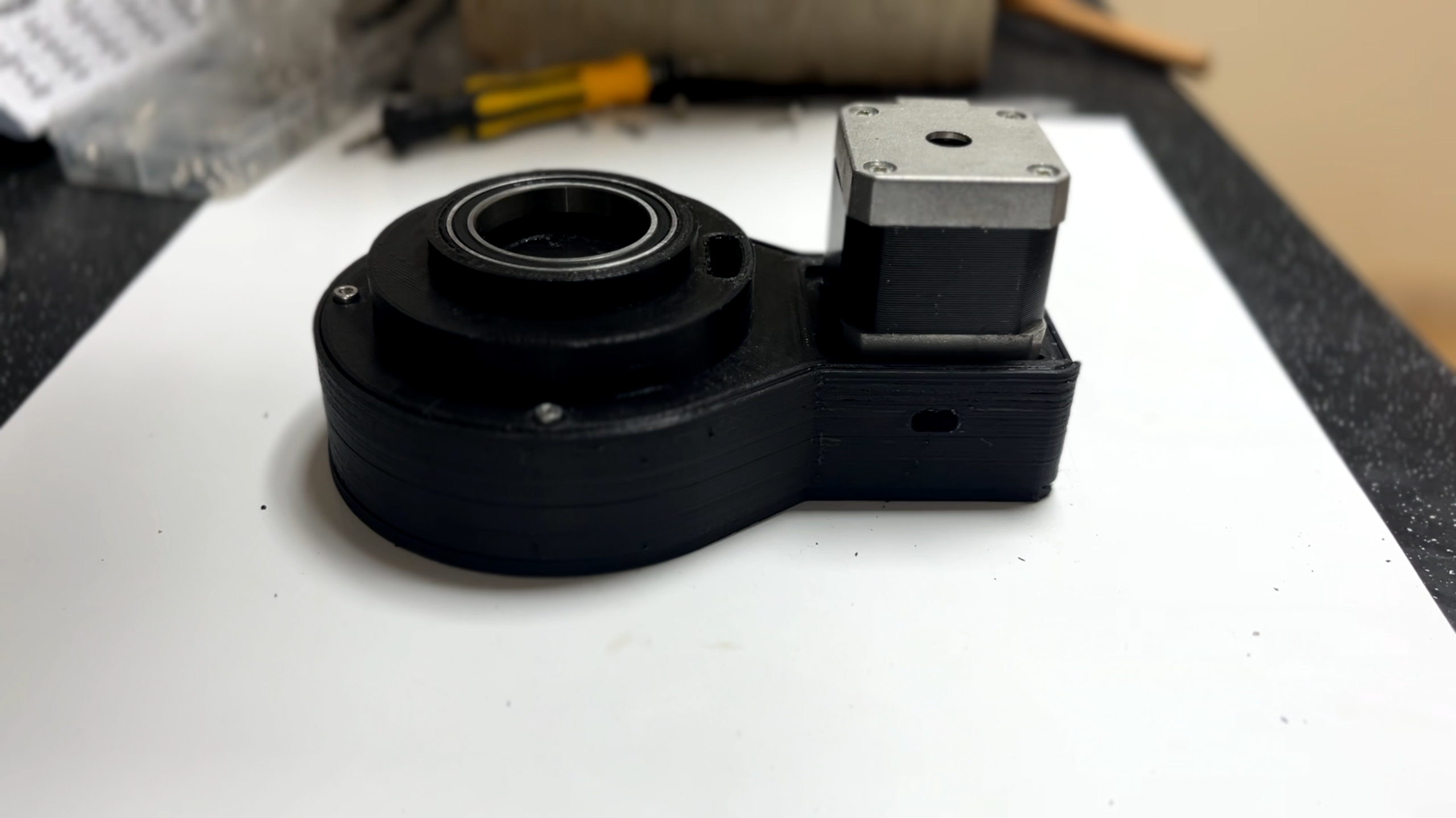
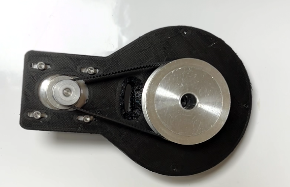
Base Assembly Engineering
Phase 04
Actuation Strategy & Torque Planning
Phase 05
Electronics Architecture

Phase 06
TO BE CONTINUED ...